UNITED STATES MARINE CORPS
Field Medical Training Battalion
Camp Lejeune
FMST 1211
Land Navigation
TERMINAL LEARNING OBJECTIVES
1. Given
a minimum of a 1:50000 military map, a coordinate scale, protractor,
paper, and pencil in a field environment, perform basic map reading, to
meet mission requirements. (FMST-FP-1211)
2. Given
a tactical scenario in any combat environment, a lensatic compass, and a minimum
of a 1:50000 military map, navigate with a map and compass to meet mission
requirements. (FMST-FP-1212)
ENABLING LEARNING OBJECTIVES
1. Without
the aid of references, given a list, identify the purpose of a military map, per
the student handout. (FMST-FP-1211a).
2. Without
the aid of references, given a list, identify the purpose of the five basic
colors on a map, per the student handout. (FMST-FP-1211b).
3. Without
the aid of references, given a list, identify the purpose of contour lines on a
military map, per the student handout. (FMST-FP-1211c).
4. Without
the aid of references, given a list, identify the parts of a lensatic compass,
per the student handout. (FMST-FP-1211d).
5. Without
the aid of references, given a military map, protractor, and compass, and a set
of eight-digit grid coordinates, locate a position on a map, per the student
handout. (FMST-FP-1211e)
6. Without
the aid of references, given a list to choose from, compute a back azimuth, per
the student handout. (FMST-FP-1211f)
7. Without
the aid of references, given a description, identify methods used to hold a
lensatic compass, per the student handout. (FMST-FP-1211g)
8. Without
the aid of references, given a military map, a lensatic compass, and a minimum
of an eight-digit grid coordinate, locate specific points on the land navigation
course, per the student handout. (FMST-FP-1212a)
9. Without
the aid of references, given a description, identify the methods used to orient
a military map, per the student handout. (FMST-FP-1212b)
1. THE
MAP
Purpose - the purpose of a
map is to provide information on the existence, the location, and the
distance between ground features.
Definition - a geographic
representation of the earth’s surface drawn to scale as seen from above.
- Shows us what an area actually looks like without being there
- A clear and handy reference tool
Characteristics of a Map
-
Designed to show us common information
-
Location of ground objects
-
Populated areas
- Routes
of travel
-
Communication Lines
- Extent of vegetation cover
- Elevation and relief of the earth's surface
Care and Importance
Maps are printed on paper and require protection from water, mud and
tearing. When you mark on your map, use lighter lines, which are easily
erased, without smearing. If trimming the map, be careful not to cut
any of the marginal information. Maps must be protected because they
can hold tactical information, such as:
-
Friendly positions
- Friendly supply points
Map Illustrations
Symbols
- The mapmaker uses standard symbols
- They represent natural and manmade features
- Resemble as closely as possible, the actual features but as viewed from above
Map Colors - to ease the identification of features
on the map, the topographic symbols are usually printed in different colors,
with each color identifying a class of features. The colors vary with different
types of maps, but on a standard, large scale, topographic map, there are five
basic colors.
Black - used to identify the majority of cultural or man-made features, such as
buildings, bridges, and roads not shown in red
Red - main roads built up areas, and special features such as dangerous or
restricted areas
Blue - is for water features: lakes, rivers, swamps, and streams
Green - identifies vegetation such as woods and orchards
Red Brown - all landforms such as contours, fills, and cuts
NOTE: Occasionally other
colors may be used to show special information. These, as a rule, will be
indicated in the “margin of information”.
Marginal Information - instructions that are placed
around the outer edges of the map are known as margin of information. All maps
are not the same, so every time a different map is used, you must examine the
margin of information carefully:
- Sheet Name - found in two places: The center of the upper margin and the lower
right margin
- Contour Interval - appears in the center lower margin and states the vertical
distance between adjacent contour lines on the map
- Grid Box - gives basic instruction on reading grids in
determination
Declination Diagram - located in the lower margin and
indicates the angular relationship of true north, grid north and magnetic north
(see figure 1):
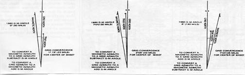
Figure 1. Declination
Diagram
- True North - a line
from any position on the earth's surface connects at the North Pole. Unlike
grid lines, all lines of longitude are true north lines.
- Magnetic North -
direction to the North Magnetic Pole, as indicated by the north-seeking needle
of a magnetic compass. The North Magnetic Pole is located in Canada at Hudson
Bay.
- Grid North - north that
is established by the vertical grid lines on the map. The variation between
grid north and true north is due to the curvature of the earth.
Grid Magnetic (GM)
Angle
- the GM angle is an important factor in map reading. The GM angle is
used to convert magnetic azimuth to grid azimuth and vice versa:
- Grid azimuth - determined with a protractor
and is measured from grid north.
- Magnetic azimuth - taken from a compass and
measured from magnetic north.
Legend
- located in the lower left margin. Illustrates and identifies some of the
symbols on the map. Every time a map is used, refer to the legend to
prevent errors in symbol identification (see figure 2). Other information
found in the legend is the Sheet Name, Sheet Number, Series Name, Edition
Number, Index to Boundaries, Index Adjoining Sheets, and Series Number.

Figure 2. Legend
Bar
Scale
- located at the center bottom of the margin, below the map face. Special
"rulers,” ground distance may be measured directly without having to convert
the map scale ratio. Normally, the scale for meters, yards, statute miles
(land) and nautical miles (sea). Easy to use, but notice that "zero" is not
at the end of the scale (see figure 3).

Figure 3. Bar Scale
2.
MEASURING DISTANCE
Straight Line Distance
- to measure line distance between two points:
- Lay a straight strip of paper on the map
so the edge touches the center on both points.
- Make a tick mark on the edge of the paper at each
point.
- Lay the paper strip along the scale that
corresponds to the unit of measure you are working with.
- Place the right tick mark of the paper strip on
the largest full unit on the primary scale (to the right of zero), allowing the
remainder to fall on the extension of the scale (to the left of zero).
Curved or Irregular
Distance
- to measure distance along a winding road, stream, or any other curved
line:
- Make a tick mark near one end of the
irregular line to be measured.
- Align the paper strip along the center of the
first straight portion of line.
- Make a tick mark at the other end of that portion
on both the paper strip and the map.
- Keeping both tick marks together, pivot the strip
at the second tick mark until another straight portion of that line is aligned.
- Continue this process until the measurement is
completed, then place the paper strip on the appropriate bar scale, and
determine the ground distance measured.
3.
PROTRACTOR
(see figure 4)
There are several types of
protractors. All of them divide the circle into units of angular measure, and
each has a scale around the outer edge and an index mark.
- The index mark is the center
of the protractor circle from which all directions are measured.
- The military protractor
contains two scales; one in degrees (inner scale) and one in mils (outer scale).
- This protractor represents
the azimuth circle.
- The degree scale is graduated
from 00 to 3600; each tick mark on the degree scale
represents one degree. A line from 00 to 1800 is called
the base line of the protractor. Where the base line intersects the horizontal
line, between 900 and 2700, is the index or center of the
protractor.
- When using the
protractor, the base line is always oriented parallel to a north-south grid
line. The 00 or 3600 mark is always toward the top or
north on the map and the 900 mark is to the right.
Figure 4.
Protractor
4. THE GRID SYSTEM
System
which tells the reader where specific locations or points are (see figure 5). A
network of lines, in the form of squares, placed on the face of the map.
These squares are somewhat like the blocks formed by the street
system of a city. The "streets" in a grid all have very simple names. The
names are all numbers. Every tenth line is made heavier in weight. This will
help you find the line you are looking for. Each grid line on the map has its
own number. These numbers appear within the map on the line itself. Four digit
numbers identify a 1000 square meter grid square. Six digits identify a
100-meter grid square. Eight digits identify a 10-meter grid square. To locate
a point by grid reference is a simple matter. We follow a simple rule of map
reading: READ RIGHT AND UP

4 Digit
Step 1 |

4 Digit
Step 2 |

6 Digit Step 3 |

8 Digit Step 4 |
Figure 5. Grid System
5.
COMPASS TERMS AND
CONCEPTS
Azimuth
- an angle measured in a clockwise direction from a north base line.
Grid Azimuth
- The heading due east is an
azimuth of 90 degrees
- South - 180 degrees
- West - 270 degrees
- North - 360 or “0” degrees.
When using an azimuth, the point from which the azimuth originates is imagined
to be the center of the azimuth circle.
Obtaining a Grid Azimuth
(a) On
your map draw a line connecting two points
- Point A represents your
present location
- Point B represents your
destination
(b)
Place the index of the protractor on point A.
(c) Ensure
the 0 degree and the 180 degree base line is parallel with the
vertical grid lines on your map.
(d)
Read the azimuth from the degree (inside) scale;
this is the grid azimuth from point A to point B.
Back
Azimuth
- Back azimuth is the
reverse direction of a forward azimuth.
- It is comparable to doing an
“about face”. To obtain a back azimuth from an azimuth less than 180 degrees,
add 180 degrees. If the azimuth is 180 degrees or more, subtract 180.
6.
Lensatic Compass
The primary instrument used to
determine and maintain direction during land navigation.
Parts of the Compass
(see figure 6)
|
- Thumb Loop
- Short luminous
Line
- Luminous
magnetic arrow, "Magnetic North"
- Sighting Slot
- Sighting Wire
- Floating Dial -
in both mils and degrees |
- Graduated
Straight Edge
-
Lens
-
Fixed Index Line
-
Bezel ring
-
Cover
-
Rear Sight
-
Base |

Figure 6. Lensatic Compass
Compass Precautions
- Handle the compass with
care. The dial is set with a delicate balance and shock could damage it.
- Reading should never be taken
near visible masses of metal or electrical circuits.
- In cold weather, always carry
the compass in its carrier outside your outer layer of clothing. If it is
carried inside of your clothing close to your body, it will fog when exposed to
the cold air.
Methods For Holding The
Compass - the
lensatic compass is used to determine or follow magnetic azimuth both day and
night. There are two recommended positions for holding the compass when
navigating:
Compass-to-Cheek
Method - recommended when determining the azimuth to a distant object.
- Raise the cover (with the sighting wire) straight
up and raise the sight (lens) to an angle about 45 degrees above the compass
glass.
- Turn the thumb loop all the way down and put your
thumb through it. Form a loose fist under the compass to steady it with your
other hand, and raise up to eye level.
- Look through the sighting slot, and align the
compass by centering the sighting wire in the sighting slot.
- Keeping the compass level and the sights aligned,
rotate your entire body until the sighting wire is aligned on a distant object.
- Now glance down through the lens and read the
magnetic azimuth under the fixed index line on the glass.
Center-Hold Position
(see figure 7)
- Recommended holding position for a
predetermined azimuth, both during the day and night.
- Do not need to remove your helmet, weapon,
grenades, or magazines as long as they are not near the compass.
- Open the cover until it forms a straight edge.
- Pull the eyepiece to the rear most position.
- Next, place your thumb through the thumb loop.
- Form a steady base with your remaining fingers.
- Using your other hand, form a solid base for your
compass.
- To measure an azimuth, simply turn your entire
body toward the object. While pointing the compass cover directly at the
object, look down and read the azimuth from beneath the black index line.

Figure 7. Center-Hold Position
Compass
Use at Night
- All the luminous features on
the compass will be used.
- The lensatic compass has two
glass faces, one under the other. The top glass (bezel ring) rotates;
each click means it has turned three degrees.
- Turn the bezel 30 clicks to
the left (counter clockwise); this is a total of 90 degrees.
- Using the center-hold method,
rotate your body and compass until the magnetic north seeking arrow is directly
aligned under the short luminous line on the bezel ring. Your compass is now
set on magnetic azimuth of 90 degrees.
- Now all you have to do to
march on this azimuth line at night is keep the magnetic north seeking arrow and
the short luminous line aligned and follow the direction of the luminous dots on
the cover of the compass.
7. ORIENTATION OF A MAP
A map is oriented when it is in position with north and south
corresponding to north and south on the ground.
Orienting a map with a compass
- With the map in a horizontal position, the compass
straight edge is placed parallel to a north-south grid with the cover of the
compass pointing toward the top of the map.
- This will place the black line on the dial of the
compass parallel to grid north.
- Since the needle on the compass points to magnetic
north, we have a declination diagram on the face of the compass formed by the
index line and the compass needle.
- Rotate the map and compass until the direction on
the declination diagram formed by the black index line and the compass needle
match the directions shown on the declination diagram printed on the margin of
the map. The map is then oriented.
- If the magnetic north arrow on the map is to the
left of grid north, the compass reading will equal the GM angle (given in the
declination diagram).
- If the magnetic north is to the right of the grid
north, the compass reading will equal 360 minus the GM angle.
Orienting Without A Compass: Terrain Association
- When a compass is not available, map orientation
requires a careful examination of the map and the ground to find linear features
common to both, such as roads, railroads, fence lines, power lines, etc.
- By aligning the feature on the map with the same
feature on the ground, the map is oriented.
- Orientation by this method must be checked to
prevent the reversal of directions that may occur if only one linear feature is
used. Aligning two or more of these features may prevent this reversal.
8. Determining
Location by Map and Compass
Basic method for determining locations on a map
Inspection and Estimation
- Usually the easiest and most simple
- Carefully survey road systems and topographical
features in the immediate vicinity.
Orient the map to the ground
- Identify some prominent characteristic such as a
road, junction, bridge, stream etc., which you can see on the ground and
unmistakably identify on your map.
9.
90 Degree Offset Method
To bypass
enemy positions or obstacles and stay oriented, detour around the obstacle by
moving at right angles for specified distances. Use this formula:
Right
add 90 degrees; Left subtract 90 degrees (RALS) (see figure 8)

Figure 8. 90 Degree Offset Method
10.
PACE COUNT
Used to keep a record of ground distance:
-
Record your count in 100-meter increments
- Step off
with your left foot and count every time it hits the deck
- Record
your 100-meter increments by putting a knot in a rope or piece of string.
(Example: A student is walking an azimuth of 25 deg. That person must travel
in this direction for 500 meters. The students pace count is 65 paces for 100
meters. To figure out how many paces the student must take – multiply your pace
count by the distance. DISTANCE divide by 100 x Pace Count (65).
11.
ELEVATION AND RELIEF
Contour Lines
- indicates elevation and relief on maps. A line representing an imaginary line
on the ground, along which all points are at the same elevation. Each contour
line represents an elevation above sea level and the amount of the contour
interval is given in the marginal information. On most maps, the contour lines
are printed red-brown, starting at zero elevation. Every fifth contour line is
a heavier brown line. These heavy lines are known as index contour lines.
Also, the elevation will be given along this heavy brown line.
- The spacing of the lines indicates the
nature of the slope. This has important military significance.
- The closer the contour
lines the steeper the terrain
Land Formations
Hill
- a point or small area of high ground (see figure 9).

Figure 9
Valley
- a stream course, which has at least, a limited extent of level ground
bordered on the sides by higher ground. Contours indicate a valley that is
a “U" shaped, and the curve of the contour crossing always points up (see
figure 10).

Figure 10
Draw -
a less developed stream in which there is essentially no level ground and
therefore, little or no maneuver room within its confines. The ground
slopes upward on each side and towards the head of the draw. Contour lines
indicating a draw are 'V" shaped, with the point of the "\/" toward the head
of the draw (see figure 11).

Figure 11
Ridge
- a line of high ground, normally with minor variations along its crest. The
ridge is not simply a line of hills but rather the ridge crest are higher than
the ground on both sides of the ridge (see figure 12).

Figure 12
Saddle
- a dip or low point along the crest of a ridge. A saddle is not necessarily
the lower ground between two hilltops; it may simply be a dip or break along an
otherwise level ridge rest (see figure 13)

Figure 13
Depression
- a low point or sinkhole surrounded on all sides by higher ground (see
figure 14).

Figure 14
Cliff
- a vertical, or near vertical, slope. When a slope is so steep that it
cannot be shown at the contour interval, it is shown by a ticked line
carrying contours. The ticks always point toward lower ground (see figure
15).

Figure 15
REFERENCES
Map Reading and Land
Navigation, FM 3-25.26, Ch 2, 6, 9, 10, 11
ITS, (May 2001), Pgs 1-18-1
through 1-18-42
Rev: July 2008
Land Navigation Review
1. List and describe the three different
types of north.
2. A six digit
grid coordinate gets you to within how many meters of your intended target?
3. Identify the
two methods for holding a compass.
4. Describe the
purpose of a contour line. |
